সোমবার, ১ নভেম্বর, ২০১০

What is Micro-controller?

Micro-Controllers:
Micro-controller is the integration of a micro-processor with memory and I/O devices, and other peripherals such as timers, on a single chip.

The general micro-controller has pins for external connections on inputs and outputs; power, clock and control signals. The pins for the inputs and outputs are grouped into I/O ports. Usually such ports have eight lines in order to be able to transfer an 8-bit word of data. Motorola 68HC11, Intel 8051 and PIC16Fxxx and PIC18Fxxx are examples of 8-bit micro-controllers.

Microcontroller Hardware:

Advantages of Micro-Controllers:
Fewer chips are required since most functions are already present on the processor chip.
Lower cost and smaller size result from a simpler design.
Lower power requirements.
Few external connections are required because most are made on-chip, and the most of the chip connections can be used for I/O
Overall reliability are higher since there are fewer components an interconnections.


Micro-Processors vs. Micro-Controllers:
  • Microprocessors are most flexible, microcontrollers are most compact.
  • Microprocessor based systems usually have a von Neuman architecture with a single memory for both programs and data to allow maximum flexibility in allocation of memory.
  • Microcontroller chips frequency embody the Harvard architecture which has separate memories for programs and data. It has the potential advantage of the separate interface allowing twice the memory transfer rate by instruction fetches to occur in parallel with data transfer.


What is Microprocessor?

Microprocessor is a device which can handle complex calculation and control strategies, it  can receive low level signal from sensors and convert to digitalwhich can be transmitted into long distance. 

Advantages of Microprocessor Based Control:
1.Low-level singal from sensors, once converted to digital, can be transmitted long distances virtually error-free.
2.A microprocessor can handle complex calculations and control stratgies.
3.Changing the control stratgey is easy by loading in a new program; no hardware changes are required.
4.Microprocessor based controllers can be easily connected to computer networks within an organization. This allows the designers to enter program changes and read current status fro their desk terminals.
5.long-term memory is available to keep track of parameters in slow-moving systems. 


Arithmetic logic unit (ALU): 
 ALU is responsible foR performing  arithmetic and logical operations. It also keeps track of status flags
that tell subsequent instructions whether the result was positive,negative, or zero, and whether an addition or subs traction operationcreated a carry or borrow.


Memory:
Microprocessors require memory resources to store programs and data. Memory can be classified two broad categories:
Volitile - loses its contents when power is turned off & Non-volatile - can retain its contents even if power is turned off.
1 Read Only Memory (ROM):
Programmable Read Only Memory (PROM)
Erasable Programmable ROM (EPROM)
Electrically Erasable Programmable ROM (EEPROM)
2 Random Access Memory (RAM):
Dynamic Random Access Memory (DRAM)
Static Random Access Memory (SRAM)
3 Other Forms of Memory:
Cache Memory
Flash Memory
Video Memory (VRAM)


Read Only Memory:
The ROM, also known as firmware, cannot be written on or erased using the computer. ROM chips contain programs that are set in at the factory; these are special instructions for computer operations. ROM chips do not loose their contents when power is removed.
PROM - can be programmed using special equipment. Once the program is written, it cannot be erased.
EPROM - are like ROM chips except that the contents can be erased, and the new data can be written. Erasure is done with a special device that uses UV light.
EEPROM - can be reprogrammed using special electrical impulses. The advantages of EEPROM chips is that they need notto be removed from the computer to be changed.

andom Access Memory:
he RAM, also known as internal memory, primary storage or
mply memory. It has three basic tasks:
1 It holds the data for processing.
2 It holds the instructions (programs).
3 It holds the data after it is processed & waiting to be sent to a
output or storage.
The contents of the RAM address locations change continually computer executes a program. It requires fast READ and WR cycle times so as no to slow down the computer operation. A major disadvantage of RAMs is that they are volatile and lo all the stored information if power is interrupted.

Other Memories:
Cache Memory - These are usually built into the MPU chip. These allows the CPU to run faster because it does not have to take time to swap instructions in and out of the RAM. The most frequently used instructions are kept in the cache memory so the CPU can look there fast.
Flash Memory - Consists of circuitry on credit-card-size card that can be inserted into slots connecting to the PC motherboard. These are non-volatile memory. These are becoming very popular in microprocessor/micro controller based applications.
Video Memory - chips used to store display images for the monitor. The amount of video memory determines how fast images appear and how many colors are available.


Input/Output Units:
The I/O operation is defined as the transfer of data between the MPU and the external world. The term peripheral devices is used for the pieces of equipment that exchange data with a MPU
system.
In input operations the input device places the data in the data register of the interface chip to hold until it is read by the MPU In output operations, the MPU places the data in the register until it is read by the peripheral.
As the speeds and characteristics of peripheral devices can differ significantly from those of the MPUs, these are connected via interface chips to synchronize data transfers between MPU and the peripheral devices.

Buses:
There are three buses external to the MPU and two buses within MPU. The external address and data buses are the extension of the same buses inside the MPU.
1. Address Bus - is a 16-line unidirectional bus that carries 16-bit address code from the MPU to the memory unit to select the memory location which the MPU is accessing for a READ or WRITE operation.
2. Data Bus - is a 8-line bidirectional bus over which 8-bit words can be sent from the MPU to the memory or from the memory to the MPU. It can carry data/instruction codes.
3. Control Bus - is grouping of all the timing and control signals needed to synchronize the operation of MPU with the other units of the microcomputer.

মঙ্গলবার, ১৯ অক্টোবর, ২০১০

Engine Lubrication System

It impossible for any engine to run efficiently without proper lubrication system.So,for safe,efficient and smooth engine operation lubrication system is must. Purposes of the lubricating system are -
1.supplies lubricating oil to all moving parts in the engine.
2.lub oil picks up engine heat and dissipates it through the oil pan.
engine lubrication system
3.oil fills the clearances between bearings and rotating journals.
4.lub oil forms a seal between piston rings and cylinder walls.
5.oil acts as a cleaning agent.

Lubricating oil is required to have the following properties-
Proper viscosity  - high viscosity oil flows too slowly and low viscosity oil has a reduced ability to stay in place - both of them may cause rapid engine wear
viscosity index (VI) - is a measure of how much the viscosity of oil changes with temperature.
viscosity numbers - single-viscosity oil has several grades - winter grade or other than winter grade.

winter grade oils are SAE 0W, SAE 5W, .., SAE 25W
other than winter grade oils are SAE 20, SAE 30, SAE 40, and SAE 50
the higher the number, the thicker the oil.

multiple-viscosity oil - has VI improver added to the oil - keeps the viscosity of oil nearly unchanged
some multi-viscosity oils are SAE 5W-30, SAE 10W-40, SAE 20W-50
resistance to carbon formation and oil oxidation.
corrosion and rust inhibitors.
detergent-dispersant's.
extreme pressure resistance.
energy-conserving oil - has friction modifiers - a chemical dissolved completely in oil or suspended carbon or molybdenum.
two types of EC oils are EC I and EC II - EC II provides better fuel-economy than an EC I oil
synthetic oil - made from carbon compounds and alcohols, or from coal and crude oil - better than petroleum based oils.

Lubrication system components:
lubrication system components
Oil pump - two types of oil pumps are used.
gear-type pump
rotor-type pump


Drive arrangement of oil pumps are:
in camshaft-in-block engines, the camshaft spiral gear that drives the ignition distributor usually drives the oil pump.
in OHC engines, the oil pump is driven by separate drive shaft - 'jackshaft'.
in distributor less engines, oil pumps are driven by crankshaft.


Oil filters:
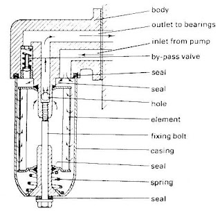
oil from the pump flows through the filter.the filter has a pleated paper filtering element.it has a spring-loaded bypass valve.some have anti-drain back valve - helps prevent oil from draining out while the engine is off.
some engines use internal oil filters - attach directly to the oil pump.

Oil pressure indicators: warn the driver if engine pressure is too low.There are four types-
indicator light - connected through an oil pressure switch - very common.
elelectric gauge - balancing coil type - the engine unit has a diaphragm connected to a sliding contact.
electronic gauge - bar graph display made up of a series of segments.

Oil level indicator (dipstick):
markings on the dipstick indicate full or add oil.some vehicles have low oil-level indicator light.Some cars have oil-change indicator light -the body control module (BCM) monitors the coolant-temperature sensor, engine speed sensor, and vehicle speed sensor.


Crankcase ventilation:
Crankcase ventilation is necessary to remove water, gasoline, and blow by gases - prevents the formation of sludge.Most recent engines use positive crankcase ventilation (PCV) system.Sludge is a thick, creamy, black substance - clogs oil screen and line.Whipping of water and oil by crankshaft creates sludge, dirt and carbon makes the colour black. Water comes into the crankcase with blow by gases and the crankcase ventilation system.Sludge forms when the engine operates cold most of the time.It forms when the cooling-system thermostat is removed.The vehicle must be driven long enough to prevent sludge
The 'normal operating temperature' vapourises water and blown away by crankcase ventilation system - thus prevents the formation of sludge.In addition to oil, other lubricants and special fluids are used in cars.Grease - a semi-solid fluid is very common made from petroleum and thickened with metallic soaps such as, Li, Ca, Na, Al, and Ba or non-metallic substance like clay .a good grease must have consistency, stability, oxidation resistance, ability to protect against friction, wear and corrosion, and feed ability.they may be-

1.wheel-bearing grease.
2.universal-joint grease.
3.chassis grease.
4.extended-lubrication interval (ELI) chassis grease.
5.multipurpose grease.
6.extreme pressure (EP) grease.
others
The engine loses oil by burning or by leaking.Three main factors resulting in 'more than normal' oil consumption are-


engine speed - high speed produces high temperature and lowers oil viscosity - oil can get into the combustion chamber and get burnt, oil-control ring can flutter or float, crankcase ventilation system takes some oil with it in the form of mist.

engine wear - such as, bearing wear, cylinder wear, piston ring wear, valve guide wear - causes more oil consumption.
engine oil can leak past the gaskets (sealing), from loose fittings, or filter

Causes of low oil pressure are:
1.A weak or broken relief valve spring.
lubrication mechanism
2.A worn oil pump .                                            
3.A broken or cracked oil line.
4.An obstruction in the oil line.
5.Insufficient or thin oil.
6.Worn engine bearings.
7.A leaking oil filter, oil filter gasket, or oil-pressure sending unit.

Excessive oil pressure results from-
1. A stuck pressure relief valve.
2.Wrong spring in the pressure relief valve.
3.A clogged oil line.
4.Thick oil.
Oil changes:
Change oil when it gets dirty or contaminated - a result of wearing out of additives
  • schedule I - change engine oil and filter every 5000 km
  • schedule II - change oil every 12,500 km and change the oil filter the first oil change and every other time after that

সোমবার, ১৮ অক্টোবর, ২০১০

Engine Cooling System

Engine Cooling System:For proper working of any engine,proper functioning of   cooling   system is
must.Cooling system ensures actual engine operation without any hazard or danger.Proper cooling system
increase engine efficiency.
engine cooling system
Cooling system performs the following three functions:    
1.it prevents overheating of the engine by removing excess heat
2.it keeps the engine at normal operating temperature
3.it provides a source of heat for the passenger compartment heater and air conditioner

Engine cooling system has five basic parts -
water jackets, water pump, thermostat, radiator, and fan


Water pump:            
cooling water pump
Water pumps are centrifugal (impeller) pumps.The pump is driven by either a belt (fan belt) from the crankshaft pulley or by gear.The pump discharge is in the order of 28,000 litres/hr.The impeller shaft is supported on sealed bearings which never need lubrication.

Engine fan:
Engine fan or cooling fan provides additional air through the radiator.The fans are either mechanical or electrical fans.The fan is made of steel sheet or moulded plastic.It has four to seven blades.A fan shroud is used to direct the air flow.Variable speed fan is sometimes used with longitudinal engines.A thermostatic fan clutch and silicone oil fluid coupling controls the speed of the engine.Flexible blade fan reduces the power needed and reduces fan noise.the pitch of the blade decreases as fan speed increases.
Electric fan is driven by an electric motor through a thermostatic switch generally transverse engines use electric fans.electric fan drains less power from the engine and usually quieter than the mechanical fans.

Radiator:
Radiator is a heat exchanger that removes heat from the engine coolant a radiator has three main parts
radiator core, and inlet and outlet tanks.the radiator core is made of aluminium and has two sets of passages, a set of tubes, and a set of fins attached to the tubes inlet and outlet tanks are made of plastic or metal.
engine radiator

Radiators may be classified according to the direction of fluid flow-
down (vertical) flow radiator: Oldest type of radiator and is designed to use the downward flow caused by natural convection
cross flow radiator:Used to make way for lower bonnet lines.Normally hot inlet is situated higher than the outlet
Sometimes transmission oil cooler is fitted with outlet tank for cars with automatic trans axle or transmission.
Some radiators have expansion tank connected by an overflow or transfer tube to the radiator filler neck.
Eliminates coolant loss by surging of the coolant during heavy braking.Prevents water from boiling during long hill climbs.Raises the working temperature thus improves engine efficiency.Allows a smaller radiator to dissipate as much heat as a larger one operating at a lower temperature.

Expansion tank:
expansion tank
expansion tank eliminates air bubbles from the coolant which makes it more efficient. Sometimes four heat exchangers are cascaded together - nearest to the engine is the cooling system radiator. Other heat exchangers are engine oil cooler, air-to-air inter cooler, and air-conditioner condenser. There are two fans in this type of cascaded system.

Thermostatic valve:
Thermostat is a heat-operated valve that regulates coolant temperature.thermostat is placed in the coolant passage between the cylinder head and the radiator.in reverse-flow cooling system, the thermostat is placed between the lower radiator hose and the engine.thermostat opens at a specific temperature, known as the thermostat rating - two common ratings are 85C and 91C

রবিবার, ১৭ অক্টোবর, ২০১০

How can we control automobile exhaust emission?

Emission Control Techniques : All types of automobile exhaust emission is harmful for our environment.so for maintain a pollution free environment automobile emission control is must.Basically there are three types of automobile emission control techniques,which are-
                                                                                                fuel tank carburetor emission
Pre-Engine System : Hot Air Intake System

In-Engine System : MPFI, EGR,λ- sensor                                         
Post-Engine System : Thermal reactor, Catalytic Converter, DPF


Manufacture needs to attain the tail pipe emission as per the standard, which
may be done involving one or more of the systems.


Thermal Reactors :
Thermal Reactor is a device which is very effective for controlling hydro carbon and carbon monoxide.
They provide more time for the exhaust at about 600°C, allowing more complete combustion of some exhaust components. Mainly involves oxidation of HC and CO.

Exhaust gas Recirculation (EGR):
Exhaust gas recirculation is another effective and efficient method for controlling automobile emission.The percentage of exhaust gas is to be recirculated can be obtain from this
equation-
EGR % = {mEGR/(mf+ma)} x 100

EGR ensures lower temperature and lower NOx formation, at the cost of –(a)lower volumetric efficiency, (b)thermal efficiency and (c)higher HC formation.
EGR is typically done at the rate of 10-15% of the intake, not exceeding 30%.EGR is done on top of the normal residual fraction of exhaust gas.EGR is not done at idling, EGR is not done at WOT.In CI engines EGR is less common as abrasive soot particles may re-enter the engine.


Catalytic Converters (CC):
Now a days catalytic converter is the most effective device for controlling automobile exhaust emission.Typically used for SI engine emission control.There are two types
of catalytic converters.they are-

2-WAY Catalytic Converter : Removes CO and HC
3-WAY Catalytic Converter : Removes NOx, CO and HC
so 3-way catalytic converter is more effective,besouse this is able to control all three types of emission.
Catalytic Converter Efficiency = {1 – (mexhaust out / mexhaust in)} x 100 %
A CC may have different removal efficiencies for different components.

Diesel Particulate Filter (DPF) :
DPF system

This is mainly use to reduce PM emissions from diesel engines.DPF consists of -(a) Metallic casing (b) Substrate(Cordie rite/SiC) (c) Regeneration system (d) Monitoring system.
As the DPF is used the pressure drop increase with time.The rate of increase depend on flow rate and particulate concentration.Monitoring system is needed to control when to start regeneration or protect the engine.

Diesel Oxidation Catalyst(DOC):
They are similar to catalytic converter.Coating of Pd/Pt are provided on the ceramics substance/honeycomb
Catalyst oxidize pollutant like HC and CO to less harmful gases.It does does not need regeneration as long the catalyst are active.For proper operation of DOC the sulphur content in diesel should be very low, at least below 500 ppm or 0.05% by weight.


selective catalytic reduction
Selective Catalytic Reduction (SCR):
SCR is the process whereby a reluctant such as ammonia or urea is mixed with NOx emissions then passed through a special flow-through catalyst to create a reduction process. During the process, the ammonia-NOx mixture is converted into harmless nitrogen and water.

শনিবার, ১৬ অক্টোবর, ২০১০

What is Catalytic Converter?


CATALYTIC CONVERTERS (CC): Catalytic converters are the most effective device to control automobile exhaust emission.This is mainly for SI engine emission control.There are two types of catalytic converter 3-way and 2-way catalytic converter.Among them 3-way catalytic converter is most effective  for controlling automobile emission.Typically used for SI engine emission control.
2-WAY Catalytic Converter :   Removes  CO and HC

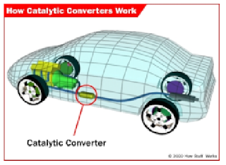
proper placement of catalytic converter
3-WAY Catalytic Converter :   Removes  NOx, CO and HC

Catalytic Converter Efficiency = {1 – (mexhaust out / mexhaust in)}   x 100 %

A CC may have different removal efficiencies for different components.


This figure is showing  the place where CC is most effective and it can work without influence of  engine temperature.For proper working of CC it need a optimum engine temperature, this is why it is necessary to
find out the place where the engine temperature is optimum.


components of catalytic converter
The Alumina wash coat ( about 20 µm) containing the noble materials is used to enhance the surface area (100-200 m2/g) of chemical reaction.


HOW CATALYTIC CONVERTER WORK: The working procedure of a catalytic converter is basically based on different catalyst and different chemical reaction which  change harmful gases into clean gases.


Catalysts (Noble metals) :         
                                
 Platinum(Pt), Rhodium (Rd),   Palladium(Pd); About 4-5 g/cat converter.
CC could be either Monolith(Honey-comb) or Pellet(Bead) type.

2-Way Catalytic Converter : Catalysts - Pt, Pd             
Oxidation reaction :     CO + O2 → CO2            HC + O2 → CO2 +H2O         

 3-Way Catalytic Converter : Catalysts - Pt, Rd, (Pd)             


catalytic converter mechanism                 


Reducing reaction :           
NO + CO → ½ N2 + CO2   2 NO + 5H2 → 2NH3 + 2H2O
NO + H2 → ½ N2 + H2O    2NO + 5CO + 3H2O → 2NH3 + 5CO2   
                                          
Oxidation reaction :     CO + O2 → CO2            HC + O2 → CO2 +H2O   

 •  3-way catalytic converters work best with engines having  precise control of air-fuel ratio. Many of them use O2 sensors incorporated at the exhaust, communicating with the engine management system.
Specially the NOx reduction reaction requires very accurate air-fuel ratio, regular carburetors and simple fuel-injection are simply too inaccurate to keep up to the requirement.
•  Catalytic converters stars working effectively as they get warm above 250-300°C. The reactions taking place are exothermic. Converter material should be able to with stand up to 1000°C. Generally heat
shields are used to protect other parts of the vehicle body.
•  Extra oxygen is needed to support the reactions, that might be provided by lean air-fuel ratio or pump-type air injection.


catalytic converter catalyst


A Catalytic Converter specification:
Engine displacement :   1.5 liter,2000cc           
Engine speed :    2000-3000  rpm
Minimum operating temperature :  250 C
Maximum allowable pressure :  800 C
Maximum allowable back pressure :  2 psi
Fuel specification :   Unleaded, S-content
Maximum pollutant in intake :  HC,CO,NOX
Pollutant reduction efficiency :  70% of HC, CO
Expected life :  100,000 km


Catalytic Converter Performance:
•  Unleaded (Pb free) fuel is essential to prevent ‘Fouling’ of Catalytic converters.
•  Most common cause of failure is an engine that pumps too much unburned fuel, which can overheat or
    carbon-clog the catalyst.
•  Fuel specification like Sulphur content should be maintained to prevent catalyst poisoning decorating
   performance.   
•  Fouling, clogging, meltdown, breakage of ceramic substance may cause a converter to stop doing its job,
    and/or plug it and raise back pressure. 
•  In most automobiles you need to use a silencer in addition the
    catalytic converter to achieve desired low noise level.

মঙ্গলবার, ১২ অক্টোবর, ২০১০

What is Gas Turbune?

Construction of Gas Turbine:
The working components of the gas turbine are assembled on a welded steel frame which also houses the fuel and lubricating oil tanks. Two doors provide access to the electrical fuses and the electronic logic and safety systems. The complete apparatus is mounted on wheels. The gas turbine consists of two principal components, the gas generator and the separate power turbine. Ancillary equipment includes two pumps (for fuel and lubricating oil) and an internally constructed start-up fan system. A new semi-automatic system for injecting alcohol during start-up is included.


Gas Generator:
The gas generator consists of a radial flow compressor of improved design, an improved combustion chamber and a radial flow turbine. The arrangement of the main components of the gas generator has been changed to reduce the length of connecting ducting and inert fiber insulation has been introduced to minimize heat loss. Air enters the compressor through an intake silencer and a venturimeter. After the compressor, the air passes through the vertical combustion chamber and then to the gas generator turbine.The speed of the compressor and turbine is measured photo-electrically and displayed on a digital counter. The gas generator may be run throughout the speed range 50,000 to 90,000 rpm and is stable at all intermediate speeds. Speed is regulated by the fuel flow control valve located on the speed control panel.


Combustion Chamber:
The combustion chamber is manufactured from 'Nimonic' steel and has been re-designed to ensure easy starting and to ensure 'clean' combustion over a wide range of running conditions. Particular attention has been paid to flame stability at light load. Pressure loss through the combustion chamber is small and the maximum continuous temperature is 700oC. The kerosene fuel is sprayed into the combustion chamber through a special nozzle and the use of a liquid fuel reduces the possibility of over-speed conditions because the fuel flow through the nozzle is automatically restricted as the compressor delivery pressure rises.

Power Turbine:
The hot gas issuing from the exhaust of the gas generator is passed through an insulated duct to the inlet of the re-designed power turbine. The power turbine is larger than the gas generator turbine and is of inward radial flow design. The shortened insulated duct connecting the gas generator to the power turbine reduces the heat losses to the atmosphere. The speed of the power turbine is measured electromagnetically and is displayed on a digital counter.The power turbine is directly coupled to the eddy current brake and the exhaust gases pass through a suitable outside wall or into a suitable exhaust gas system. The low gas velocities through the power turbine ensure that exhaust noise level is sufficiently low to avoid the need for a silencer.


Fuel System:
Kerosene is the operating fuel.Fuel is pumped by an electrically driven gear pump and at pressure of 6 bars (90 psi) from fuel tank. The fuel flow is regulated by a manual valve located in the control panel and is measured by a 'Rotameter'. During the start sequence methylated alcohol or methanol is automatically injected and is ignited by the high energy spark system. The alcohol flame then ignites the kerosene.

Lubricating Oil System:
A self-contained lubricating oil system is provided which includes a water cooled oil cooler and the necessary filters. Instruments are provided to indicate lubricating oil temperature and pressure.

Semi-Automatic Starting System:
Four electrically driven fans, built into the intake silencer, provide a flow of air through the gas generator during the start sequence. Alcohol is gravity fed to the combustion chamber and controlled by a solenoid valve. The alcohol is ignited by the high energy spark system and during this stage of the start only one of the four electrically driven fans is in use. When a flame is detected (as shown by one of the temperature indicators) the fuel pump is switched on. An automatic system then switches on the remaining fans and admits the correct amount of kerosene to achieve an idling speed on the gas generator of 45/50,000 rpm. The manual control valve is then used to increase the speed to 55/60,000 rpm and the fans can be turned off. Throughout the start sequence indicator lights show what is happening such as: number of fans in use, alcohol present in combustion chamber, high energy spark on, etc

Safety Equipment:This test set is designed for safe and accurate experimental work by students without continuous supervision. A comprehensive system of safety devices has been incorporated to ensure that the apparatus will shut down automatically if any of the following faults develop-
1. Low lubricating oil pressure.
2. High combustion chamber outlet temperature.
3. Mains electricity failure.
A warning light is provided to indicate excessive temperature in the eddy current brake. The complete starting and shut-down sequence is controlled by a system of electrical and electronic logic devices which will only permit the correct sequence of starting to be used and which will also automatically switch on the starting fans to cool the machine after shut-down at the end of an experiment or after automatic shut-down resulting from a malfunction.